




大小:247.41 MB
格式:PDF
语言:英语
品牌:三一 (Sany)
设备类型:旋挖钻机
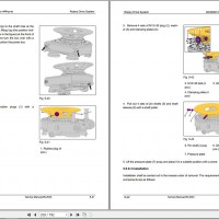
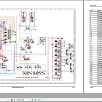
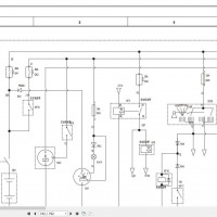
手册类型:维修手册、电气与液压原理图
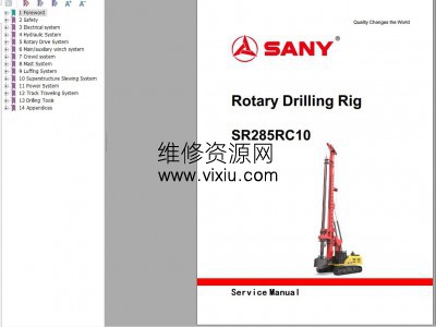
型号:三一 SR285RC10 旋挖钻机
发布日期:2023年
页数:792页
Contents:
1 Foreword
1.1 Service Manual Reading Guide
1.2 Explanation of Standard Maintenance Terminology
1.3 Basic Principles for Maintenance
1.4 Precautions for Handling Electrical and Hydraulic Components
1.4.1 Overview
1.4.2 Precautions for Handling Electrical Parts
1.4.3 Precautions for Handling Hydraulic Parts
1.5 Precautions for Tightening Pipe Connectors
1.5.1 Overview
1.5.2 Pipe Fitting Types
1.5.3 Pipe Fitting Tightening Torque
1.5.4 O-ring Connection
1.6 Precautions for Tightening Bolts and Nuts
1.6.1 Bolt Type
1.6.2 Bolt Tightening Sequence
1.6.3 Bolt and Nut Tightening Torque
1.7 Precautions for Tightening Split Flanges
1.7.1 Overview
1.7.2 Tightening Torque for Split Flange Bolts
1.8 Unit Conversion Table
2 Safety
2.1 Safety Signs
2.2 General Precautions
2.2.1 Overview
2.2.2 Safety Rules
2.2.3 Keep the Work Area Clean
2.2.4 Precautions for Fluid Storage
2.2.5 Precautions for Part Cleaning
2.2.6 Precautions for Cleaning Machine
2.2.7 Precautions for Maintenance Attire
2.2.8 Precautions for Using Maintenance Tools
2.2.9 Familiarize with Fire Extinguisher and Emergency Exit Location
2.3 Preparations before lowering the jib boom
2.3.1 Pre-Maintenance Preparations
2.3.2 Warning Signs
2.3.3 Self-Preparation
2.4 Precautions During Maintenance
2.4.1 Precautions for Maintenance During Engine or Motor Operation
2.4.2 Precautions for Motor and Electric Control Maintenance
2.4.3 Precautions for Removing Machine Attachments
2.4.4 Precautions for Aligning Parts
2.4.5 Precautions for Maintenance Under the Machine
2.4.6 Precautions for Using Hammers
2.4.7 Precautions for Using Compressed Air
2.4.8 Precautions for Welding
2.4.9 Precautions for Track Maintenance
2.4.10 Precautions for Adding or Replacing Oils and Fluids
2.4.11 Precautions for Repairing High-Pressure Hose
2.4.12 Beware of the High-Pressure Fluids
2.4.13 Beware of Hot Coolant
2.4.14 Precautions for Air Conditioner Maintenance
2.4.15 Electrical Safety During Maintenance
2.4.16 Precautions for Battery Maintenance
2.4.17 Precautions for Accumulator Maintenance
2.4.18 Avoiding Fire and Explosion Hazards
2.4.19 Proper Waste Disposal
2.4.20 Precautions for Lifting Operations and Signaling
2.4.21 Precautions for Using Mobile and Bridge Cranes
2.4.22 Selecting Wire Rope
2.4.23 Additional Precautions
2.5 Precautions for Fault Diagnosis
2.5.1 Pre-Troubleshooting Inspection
2.5.2 Precautions for Troubleshooting
2.5.3 Procedures for Troubleshooting
2.5.4 Troubleshooting Categories and Steps
3 Electrical system
3.1 Working Principle
3.1.1 Main pump
3.1.2 Pilot
3.1.3 Depth measurement
3.1.4 Power-on - start - delayed power off
3.1.5 A/C and radio
3.1.6 Wiper and washer
3.2 Terminal insertion and removal
3.3 DTC
3.3.1 Service code list
3.3.2 E001-Open circuit of hydraulic fan 1 signal
3.3.3 E033-Open circuit of throttle knob signal
3.3.4 E037-Open circuit of main pump power control valve
3.3.5 E049-Main winch pin shaft tension open circuit
3.3.6 E051-Open circuit of leveling handle Y axis
3.3.7 E053-Open circuit of crowding pressure sensor
3.3.8 E055-Open circuit of mast lever X axis
3.3.9 E057-Open circuit of mast left retraction proportional valve
3.3.10 E059-Mast left extension proportional valve open circuit
3.3.11 E061-Open circuit of mast right retraction proportional valve
3.3.12 E063-Open circuit of mast right extension proportional valve
3.3.13 E065-Open circuit of crowding adjusting proportional valve
3.3.14 E091-Open circuit of rotary drive torque
3.3.15 E093-Left joystick push/pull signal open circuit
3.3.16 E095-Right joystick push/pull signal open circuit
3.3.17 H001-Main pump 1 pressure too low
3.3.18 H003-Main pump 2 pressure too low
3.3.19 H023-Excessively low pressure of working device
3.3.20 H025-Excessively low traveling pressure
3.3.21 DTC P0016 (flashing code 16) phase mismatching of camshaft sensor
3.3.22 DTC P0087 (flashing code 225) pressure limiting valve open
3.3.23 DTC P0089 (flashing code 151) abnormal common rail pressure (pump overpressure delivery)
3.3.24 DTC P0091 (flashing code 247) disconnection of PCV1 driving system or GND short circuit
3.3.25 DTC P0092 (flashing code 217) short circuit of PCV1 driving system + B
3.3.26 DTC P0093 (flashing code 227) abnormally low pressure of common rail pressure (pump delivery without pressure 2\in cold state)
3.3.27 DTC P0112 (flashing code 22) abnormal intake air temperature sensor (abnormally low voltage)
3.3.28 DTC P0113 (flashing code 22) abnormal intake air temperature sensor (abnormally high voltage)
3.3.29 DTC P0117 (flashing code 23) abnormal water temperature sensor (abnormally low voltage)
3.3.30 DTC P0118 (flashing code 23) abnormal water temperature sensor (abnormally high voltage)
3.3.31 DTC P0182 (flashing code 211) abnormal fuel temperature sensor (abnormally low voltage)
3.3.32 DTC P0183 (flashing code 211) abnormal fuel temperature sensor (abnormally high voltage)
3.3.33 DTC P0192 (flashing code 245) Abnormal common rail pressure sensor (abnormally low voltage)
3.3.34 DTC P0193 (flashing code 245) Abnormal common rail pressure sensor (abnormally high voltage)
3.3.35 DTC P0201 (flashing code 271) disconnection of injector #1 driving system
3.3.36 DTC P0202 (flashing code 272) disconnection of injector #2 driving system
3.3.37 DTC P0203 (flashing code 273) disconnection of injector #3 driving system
3.3.38 DTC P0204 (flashing code 274) disconnection of injector #4 driving system
3.3.39 DTC P0205 (flashing code 275) disconnection of injector #5 driving system
3.3.40 DTC P0206 (flashing code 276) disconnection of injector #6 driving system
3.3.41 DTC P0217 (flashing code 542)overheating
3.3.42 DTC P0219 (flashing code 543)overdriving
3.3.43 DTC P0237 (flashing code 32)abnormal boost pressure sensor (abnormally low voltage)
3.3.44 DTC P0238 (flashing code 32)abnormal boost pressure sensor (abnormally high voltage)
3.3.45 DTC P0335 (flashing code 15)abnormal crankshaft sensor (no signal)
3.3.46 DTC P0336 (flashing code 15)abnormal crankshaft sensor (abnormal signal)
3.3.47 DTC P0340 (flashing code 14)abnormal camshaft sensor (no signal)
3.3.48 DTC P0380 (flashing code 66) abnormal preheating relay
3.3.49 DTC P0381 (flashing code 67) abnormal preheating indicator
3.3.50 DTC P0404 (flashing code 45) EGR valve control abnormality
3.3.51 DTC P0409 (flashing code 44) abnormal EGR position sensor
3.3.52 DTC P0522 (flashing code 295) abnormal engine oil pressure sensor (abnormally low voltage)
3.3.53 DTC P0523 (flashing code 295) abnormal engine oil pressure sensor (abnormally high voltage)
3.3.54 DTC P0563 (flashing code 35) abnormally high voltage of battery
3.3.55 DTC P0601 (flashing code 53) abnormal ROM
3.3.56 DTC P0602 (flashing code 154) abnormal QR code
3.3.57 DTC P0604 (flashing code 153) abnormal RAM
3.3.58 DTC P0606 (flashing code 51) abnormal CPU/abnormal IC for CPU monitoring
3.3.59 DTC P060B (flashing code 36) abnormal A/D switching
3.3.60 DTC P0615 (flashing code 19) abnormal disconnection relay of starter motor
3.3.61 DTC P0641 (flashing code 55) abnormal voltage of 5 V power supply 1
3.3.62 DTC P0650 (flashing code 77) abnormal fault indicator
3.3.63 DTC P0651 (flashing code 56) abnormal voltage of 5 V power supply 2
3.3.64 DTC P0685 (flashing code 416) abnormal main relay (unable to be connected)
3.3.65 DTC P0687 (flashing code 416) abnormal main relay (unable to be disconnected)
3.3.66 DTC P0697 (flashing code 57) abnormal voltage of 5 V power supply 3
3.3.67 DTC P1062 (flashing code 257) abnormal PCV1 FLY BACK
3.3.68 DTC P1063 (flashing code 258) abnormal PCV2 FLY BACK
3.3.69 DTC P1093 (flashing code 226) abnormally low pressure of common rail pressure (pump delivery without pressure 1\in cold state)
3.3.70 DTC P1112 (flashing code 295) abnormal boost temperature sensor (abnormally low voltage)
3.3.71 DTC P1113 (flashing code 295) abnormal boost temperature sensor (abnormally high voltage)
3.3.72 DTC P1261 (flashing code 34) abnormal charging circuit (Bank 1)
3.3.73 DTC P1262 (flashing code 34) abnormal charging circuit (Bank 2)
3.3.74 DTC P1293 (flashing code 211) abnormal fuel filter clogging sensor (abnormally low voltage)
3.3.75 DTC P1294 (flashing code 221) abnormal fuel filter clogging sensor (abnormally high voltage)
3.3.76 DTC P1404 (flashing code 45) abnormal EGR zero learning
3.3.77 DTC P1621 (flashing code 54) abnormal EEPROM
3.3.78 DTC P1655 (flashing code 59) abnormal voltage of 5 V power supply 4
3.3.79 DTC P2122 (flashing code 121) abnormal throttle opening sensor 1 (abnormally low voltage)
3.3.80 DTC P2123 (flashing code 121) abnormal throttle opening sensor 1 (abnormally high voltage)
3.3.81 DTC P2127 (flashing code 122) abnormal throttle opening sensor 2 (abnormally low voltage)
3.3.82 DTC P2128 (flashing code 122) abnormal throttle opening sensor 2 (abnormally high voltage)
3.3.83 DTC P2138 (flashing code 124) abnormality upon comparison between throttle opening sensors 1 and 2
3.3.84 DTC P2146 (flashing code 158) abnormal driving system of injector COMMON 1
3.3.85 DTC P2149 (flashing code 159) abnormal driving system of injector COMMON 2
3.3.86 DTC P2228 (flashing code 71) abnormal atmospheric pressure sensor (abnormally low voltage)
3.3.87 DTC P2229 (flashing code 71) abnormal atmospheric pressure sensor (abnormally high voltage)
3.3.88 DTC P2295 (flashing code 248) disconnection of PCV2 driving system or GND short circuit
3.3.89 DTC P2296 (flashing code 218) short circuit of PCV2 driving system + B
3.3.90 DTC U0001 (flashing code 84) abnormal ISO-CAN Bus
3.3.91 DTC U0073 (flashing code 84) abnormal CAN Bus
3.3.92 DTC U0101 (flashing code 85) abnormal CAN timeout
3.3.93 DTC U2106 (flashing code 85) abnormal Wheel Loader CAN timeout
3.4 Fault Cases
3.4.1 The construction data displayed on EVI platform are all 0
3.4.2 EVI data not displayed
3.4.3 Camera fault
3.4.4 Communication fault and display stays on all the time
3.4.5 Analysis and solution of screen fault
3.4.6 Analysis and solution of tension display fault
3.4.7 Analysis and solution of depth measurement fault
3.4.8 Analysis and solution of no movement of the machine
4 Hydraulic System
4.1 Main oil pump operating principle
4.2 Testing and Adjustment
4.2.1 Test and adjustment of overflow pressure of main valve
4.2.2 Test and adjustment of auxiliary valve overflow pressure
4.2.3 Release the residual pressure in the hydraulic oil lines
4.2.4 Air bleeding of devices
4.3 Removal and Installation
4.3.1 Removal and installation of hydraulic pump assembly
4.3.2 Removal and installation of main valve assembly
4.3.3 Removal and installation of auxiliary valve assembly
4.3.4 Removal and installation of hydraulic oil tank assembly
4.3.5 Removal and installation of eight-way solenoid valve group
4.3.6 Removal and installation of quadruple solenoid valve group
4.3.7 Removal and installation of pilot filter
4.3.8 Breather Valve - Remove and Install
4.3.9 Removal and installation of oil suction filter element cover plate
4.3.10 Removal and installation of oil return filter cover plate
4.3.11 Removal and installation of the hydraulic cylinder assembly
5 Rotary Drive System
5.1 Overview
5.2 Mechanical principle
5.3 Electrical Working Principle
5.3.1 Rotary drive positive/reverse rotation
5.4 Hydraulic principle: Rotary drive forwarding or reversing
5.5 Testing and Adjustment
5.5.1 Test and adjustment of rotary drive positive/reverse rotation relief pressure
5.5.2 Test of oil charge pressure of rotary drive motor
5.6 Removal and Installation
5.6.1 Rotary Drive Crowd Sledge - Remove and Install
5.6.2 Rotary Drive Connecting Plate - Remove and install
5.6.3 Removal and installation of rotary drive buffer key sleeve
5.6.4 Rotary Drive Motor Reducer - Remove and Install
5.6.5 Rotary Drive Air Filter - Remove and Install
5.6.6 Rotary Drive Pressure Plate - Remove and Install
5.7 Fault Cases
5.7.1 Rotary drive low speed fault
5.7.2 Rotary drive rotation speed fluctuation fault
5.7.3 Abnormal sound of rotary drive reducer
5.7.4 No display of rotary drive speed
5.7.5 No display of rotary drive torque
6 Main/auxiliary winch system
6.1 Overview
6.2 Mechanical principle
6.3 Electrical Working Principle
6.3.1 Main winch freefall brake and brake release
6.3.2 Main winch lifting/lowering
6.3.3 Main winch freefall
6.3.4 Auxiliary winch lifting/lowering
6.3.5 Main/auxiliary winch limit
6.4 Hydraulic Working Principle
6.4.1 Main winch lifting/lowering
6.4.2 Main winch freefall
6.4.3 Auxiliary winch lifting/lowering
6.5 Testing and Adjustment
6.5.1 Test and adjustment of main winch relief pressure
6.5.2 Test of brake valve oil port Br pressure of main winch motor
6.5.3 Test and adjustment of relief pressure of auxiliary winch
6.5.4 Auxiliary winch motor brake pressure test
6.6 Removal and Installation
6.6.1 Removal and installation of main winch assembly
6.6.2 Removal and installation of auxiliary winch assembly
6.6.3 Disassembly and assembly of rope hold-down roller
6.7 Fault Cases
6.7.1 Main winch freefall disabled
6.7.2 No movement of main winch lowering
6.7.3 No movement of main winch lifting
6.7.4 Main winch lifting/lowering has no movement
6.7.5 The wire rope on main winch is not well braked
6.7.6 The main winch shakes during the Kelly bar lowering
7 Crowd system
7.1 Overview
7.2 Electrical Working Principle
7.2.1 Crowding/pulling
7.2.2 Crowding limit (if any)
7.3 Hydraulic principle: Crowding/pulling
7.4 Test and adjustment of overflow pressure of crowd cylinder
7.5 Removal and Installation
7.5.1 Removal and installation of crowd cylinder assembly
7.5.2 Disassembly and assembly of crowd cylinder
7.6 Fault Cases
7.6.1 Abnormal noise and difficult pressurization of crowd cylinder
7.6.2 No movement of crowd cylinder
7.6.3 Abnormal noise during cylinder retraction
7.6.4 Automatic pressure relief of crowd cylinder
8 Mast System
8.1 Overview
8.2 Mechanical principle
8.3 Electrical Working Principle
8.3.1 Manual lowering/raising the mast
8.3.2 Auto mast lowering/rasing
8.3.3 Inching mast adjustment
8.3.4 Auto adjusting
8.3.5 Mast limit
8.3.6 Masthead cylinder extension/retraction
8.4 Hydraulic Working Principle
8.4.1 Lowering mast and raising mast
8.4.2 Masthead cylinder extension and retraction
8.5 Testing and Adjustment
8.5.1 Test and adjustment of overflow pressure of mast cylinder
8.5.2 Test and adjustment of overflow pressure of masthead cylinder
8.6 Removal and Installation
8.6.1 Masthead - Remove and install
8.6.2 Mast Pivot Assembly - Remove and Install
8.6.3 Mast Cylinder - Remove and Install
8.6.4 Mast Cylinder - Disassemble and Assemble
8.7 Fault Cases
8.7.1 No movement of mast
8.7.2 No movement of mast right cylinder
8.7.3 Left tilt of the mast
9 Luffing System
9.1 Overview
9.2 Mechanical principle
9.3 Electrical Working Principle
9.3.1 Derricking mechanism lifting/lowering
9.3.2 Derricking limit
9.4 Hydraulic principle: Boom up and down
9.5 Test and adjustment of boom cylinder overflow pressure
9.6 Removal and Installation
9.6.1 Removal and installation of triangle
9.6.2 Boom - Remove and Install
9.6.3 Removal and installation of support arm and derricking cylinder
9.6.4 Derricking Cylinder - Disassemble and Assemble
9.7 Fault Cases
9.7.1 Weak derricking action
9.7.2 Abnormal derricking movement
9.7.3 Derricking mechanism pressure relief
9.7.4 Reverse derricking movement
10 Superstructure Slewing System
10.1 Overview
10.2 Electrical Working Principle
10.2.1 Left/right swing
10.3 Hydraulic Working Principle
10.3.1 Upper carriage left/right swing and swing buffering
10.4 Testing and Adjustment
10.4.1 Test and adjustment of upper carriage swing overflow pressure
10.4.2 Test and adjustment of A/C system
10.5 Removal and Installation
10.5.1 Removal and installation of swing motor
10.5.2 Removal and installation of swing reducer
10.5.3 Removal and installation of swing joint assembly
10.5.4 Disassembly and assembly of central swing joint assembly
10.5.5 Removal and installation of swing bearing assembly
10.5.6 Removal and installation of counterweight assembly
10.5.7 Disassembly and assembly of water radiator cover
10.6 Fault Cases
10.6.1 The swing angle not displayed
10.6.2 The swing mechanism cannot be locked
10.6.3 The machine can not swing
11 Power System
11.1 Outline diagram of each system
11.2 Testing and Adjustment
11.2.1 Exhaust smoke measurement
11.2.2 Check the compression pressure of engine
11.2.3 Test and tension adjustment of belt
11.3 Removal and Installation
11.3.1 Removal and installation of fuel tank assembly
11.3.2 Removal and installation of the radiator assembly
11.3.3 Removal and installation of coupling
11.3.4 Removal and installation of damper pad and engine support
11.3.5 Removal and installation of engine oil filter assembly
11.3.6 Removal and installation of fuel pre-filter assembly
11.3.7 Removal and installation of fine fuel filter assembly
11.3.8 Removal and installation of water oil separator assembly
12 Track Traveling System
12.1 Overview
12.2 Electrical Working Principle
12.2.1 Crawler travel
12.2.2 Crawler extension/retraction
12.3 Hydraulic Working Principle
12.3.1 Travel
12.3.2 Crawler extension and retraction
12.4 Testing and Adjustment
12.4.1 Test and adjustment of overflow pressure of extension cylinder
12.4.2 Test and adjustment of relief pressure of traveling motor
12.4.3 Inspection and adjustment of track shoe tensioning device
12.4.4 Measurement of traveling offset
12.5 Removal and Installation
12.5.1 Removal and installation of travel motor reducer
12.5.2 Removal and installation of carrier rollers
12.5.3 Removal and installation of idler and tensioner
12.5.4 Removal and installation of crawler assembly
12.5.5 Removal and installation of sprockets
12.5.6 Removal and installation of carrier roller
12.6 Fault Cases
12.6.1 It cannot travel (only on one side)
12.6.2 The machine has off-tracking during traveling
13 Drilling Tools
13.1 Introduction to Kelly bar
13.1.1 Friction bar
13.1.2 Mechanical locking drill pipe
13.2 Disassembly of Kelly bar
13.3 Assembly of Kelly bar
13.4 Kelly Bar Fault Diagnosis
13.4.1 Maintenance list
13.4.2 Requirements for maintenance technique
13.4.3 List of consumables
13.4.4 Common faults and maintenance
13.4.5 Key Faults and Maintenance
14 Appendices
14.1 Harness Diagram
14.1.1 Harness diagram: right platform harness
14.1.2 Harness diagram: mast harness
14.1.3 Harness diagram: upper mast harness
14.1.4 Harness diagram: cab harness
14.1.5 Harness diagram: masthead harness
14.1.6 Harness diagram: rotary drive harness
14.1.7 Harness diagram: rotary drive machine body harness
14.1.8 Harness diagram: electric cabinet harness
14.1.9 Harness diagram: machine body harness
14.1.10 Harness diagram: machine body pipeline harness
14.2 Electrical schematic diagram
14.3 Codes list of electrical components
14.4 Hydraulic schematic(rotary drive with brake valve)
14.5 Hydraulic schematic(rotary drive without brake valve)
14.6 Hydraulic schematic(rotary drive with Rexroth and Kawasaki motor)
14.7 Electrical components - sensor
14.7.1 Depth measurement sensor BG1
14.7.2 Mast inclination sensor BG3
14.7.3 Main winch line pull sensor BP19
14.7.4 Mast left limit switch SF2
14.7.5 Mast right limit switch SF3
14.7.6 Main winch limit switch SF4
14.7.7 Auxiliary winch limit switch SF5
14.8 Electrical components - solenoid valve
14.8.1 Quadruple valve group solenoid valve DT10-DT11, DT13-DT14
14.9 Hydraulic components: hydraulic pump
14.9.1 V1 Pump unit
14.10 Hydraulic components- valve group
14.10.1 V2 Main valve group
14.10.2 V3 auxiliary valve group
14.10.3 V4 four-way valve group
14.10.4 V5 pedal pilot valve
14.10.5 V6 left handle pilot valve
14.10.6 V7 right handle pilot valve
14.10.7 V11 Fourteen-way valve group
14.10.8 V18 Main winch freefall valve group
14.10.9 V19 Opening valve group of main winch brake cylinder
14.10.10 V21 Crowd cylinder balance valve
14.10.11 V22, V23, V24, and V25 mast cylinder balance valves
14.10.12 V26, V27, V28, and V29 derricking cylinder balance valves
14.10.13 V30 masthead cylinder balance valve
14.10.14 V64 Main winch balance valve group
14.11 Hydraulic components - motor
14.11.1 V40 and V41 rotary drive motor assembly
14.11.2 V43 main winch motor assembly
14.11.3 V45 auxiliary winch motor assembly
14.11.4 V47 swing motor assembly
14.11.5 V49 and V50 left and right travel motor assemblies
14.11.6 V51 Radiator motor assembly
14.12 Hydraulic parts - cylinder
14.12.1 MC1 crowd cylinder
14.12.2 MC2 and MC3 left/right mast cylinder
14.12.3 MC4 and MC5 derricking cylinders
14.12.4 MC6, MC7, MC8 and MC9 crawler telescopic cylinders
14.12.5 MC10 Masthead cylinder
14.13 Hydraulic parts- others
14.13.1 EP1 radiator
14.13.2 V52 center swing joint
14.13.3 V53 rotary drive oil seat assembly
14.13.4 V54 hydraulic oil tank assembly
14.13.5 V58 air filter
14.13.6 V57 pilot filter
